Scale Model Shop

Collapse

Wardell Bridge

Collapse
This topic is closed.
X
X
 
  • Time
  • Show
Clear All
new posts
  • Peter
    • Mar 2017
    • 96

    #31
    I may have solved a problem with using servo motors for opening and closing the bridge gates. I never used servos before, but their data sheets say they can rotate fairly quickly. Too quick for my liking. If I used the servos as is, the gates would swing 90 in a very snappy way. My options are limited to what the museum budget allows. So to use reduction gearing requires delicate gearbox housing construction. And the slowest servos are used with model sailing boats, and they cost a fair bit.

    Normally, to vary the speed of a DC motor, the voltage supplied to the motor is chopped (pulsed). Pulse-Width Modulation (PWM) is used. However, servo motors use PWM for servo arm positioning. So PWM cannot be used, as well, for speed control.

    While designing a lever system for operating the gates I saw a way around my problem. The gate has to swing 90 deg, and the standard servo rotates 180 deg. Using different length drive arms for servo and gate axle, a change of speed, or more correctly 'time', can be accomplished. The time for the servo to travel 180 deg can be the same for a gate travelling 90 deg. That is half the speed (though not at a regular pace [deg per millisecond]).

    This is my plan. (please note, sometimes my plans don't work out).
    [ATTACH]278565[/ATTACH]
    Attached Files

    Comment

    • Guest

      #32
      I knew that, " what did he say " lol.
      Outstanding build Peter way over my head mate, looking forward to the next installment.

      John

      Comment

      • Peter
        • Mar 2017
        • 96

        #33
        Thanks John.

        Comment

        • Peter
          • Mar 2017
          • 96

          #34
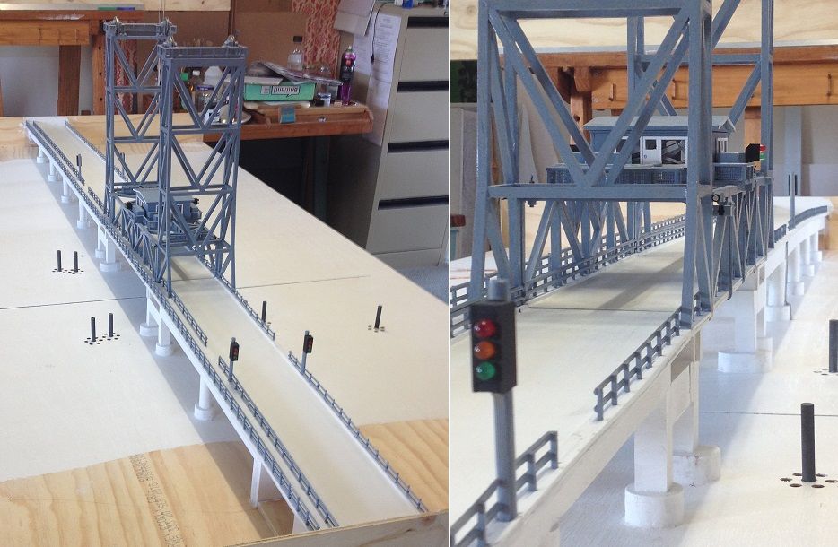
          Finally got the bridge railings painted.

          Comment

          • Ian M
            Administrator
            • Dec 2008
            • 18271
            • Ian
            • Falster, Denmark

            #35
            Looking very nice. I do though have a question that stems form my ignorance.
            The way my mind works, a big gear on the motor and a smaller gear on the wheel normally makes the wheel go faster with less torque. (thinking bicycle wheels here).
            Surly this would mean to get the faster servo to lift the 'heavy' bridge you would need a small gear on the servo and a large one on the bridge section.
            But these are just my thoughts, so probably way off the target. lol
            Would a small motor and a couple of mini switches not do the job?
            Group builds

            Bismarck

            Comment

            • Snowman
              SMF Supporters
              • Oct 2014
              • 2098

              #36
              A reduction gearing is the best option if you are using a fast motor - small drive gear (pinion drive) to large driven gear. If a slow, high torque motor is used then no reduction should be required unless only for scaling.

              Comment

              • Peter
                • Mar 2017
                • 96

                #37
                Hi Ian.
                To clarify, the servo is only for the swing gates. These gates will be located in those gaps you see, near the traffic lights, in the above photograph. The servos are positional type and will be set to only turn 90 deg.

                You are right about using a small gear on the servo motor, to drive a larger gear for slower revolutions and greater torque. But to do this requires reasonable accurate assemble of a gear box (even for one gear). My thinking is to simply use a lever system as described in post # 31.

                The bridge motor is a standard DC motor with a 148:1 gear box ratio. The output shaft rotates at o.77 r.p.sec (1 rev per 1.3 seconds) . Bridge span speed will mainly depend on the drive pulley diameter, which winds the cable in and out. If this is still too fast, I will simply put a DC motor speed controller on the motor, and set it for the desired rate of span lift.

                Has my explanation helped? If not please feel free to ask any question or give any suggestion for consideration. I welcome any thoughts and feedback.

                Comment

                • Peter
                  • Mar 2017
                  • 96

                  #38
                  Originally posted by Snowman
                  A reduction gearing is the best option if you are using a fast motor - small drive gear (pinion drive) to large driven gear. If a slow, high torque motor is used then no reduction should be required unless only for scaling.
                  Thanks Snowman. Your quote is true, and just beat me to the post.

                  Comment

                  • Mr Bowcat
                    SMF OG
                    • Dec 2016
                    • 4605
                    • Bob
                    • London

                    #39
                    What a truly epic build, good going.

                    Bob
                    Si vis pacem, para bellum.

                    Comment

                    • Guest

                      #40
                      Wow I'm gobsmacked, that is an epic and awesome build, and all this technical talk just flies right over my head.
                      Amazing.

                      Comment

                      • Peter
                        • Mar 2017
                        • 96

                        #41
                        Thank you Bob, and kpnuts, for your comments.

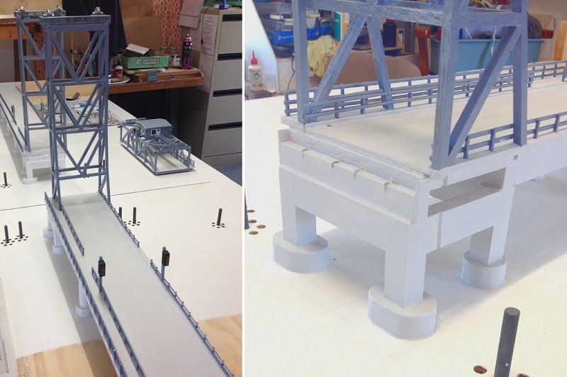
                        I am currently painting the rest of the bridge a cement colour (light grey). I looks like its going to need a few coats.
                        Afterwards I will experiment with splattering darker grey colours on the road base to make it look like concrete (fingers-crossed). I am a bit apprehensive about that.

                        Comment

                        • Peter
                          • Mar 2017
                          • 96

                          #42
                          After three coats of paint I am happy with the fresh concrete look.
                          I am not going to show any weathering. As a lad, during one summer holiday, I worked three months for an architectural renderer. From this, I have come to like clean coloured images with no signs of pollution. So my diorama, hopefully, will be likewise.

                          Comment

                          • Peter
                            • Mar 2017
                            • 96

                            #43
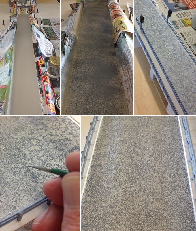
                            Started painting the road by splattering dark grey paint on the cement coloured road. Some areas became over splattered.
                            Then I dry brushed the dark areas with cement colour and the light areas with dark grey.
                            Followed by pointillising the patches in the same way, until it all looked fairly even.

                            Comment

                            • Guest

                              #44
                              extraordinary !!
                              you are awesome

                              Comment

                              • Peter
                                • Mar 2017
                                • 96

                                #45
                                Thank you cuneyt for your comment.

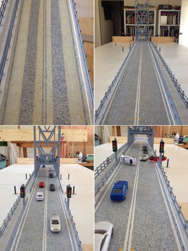
                                Finally painted the road surface for the span section. It was tricky.
                                Also painted the road markings and installed road reflectors.

                                Bottom pictures: I was playing around with 1/72 scale cars.

                                Comment

                                Working...