Scale Model Shop

Collapse

Sherman V at Westkapelle, ca. 1947

Collapse
X
 
  • Time
  • Show
Clear All
new posts
  • Guest

    #1

    Sherman V at Westkapelle, ca. 1947

    This is a repost of a thread I originally started on the Military Modelling forums, so some of you may have seen this already. I’ll recreate the posts I made then, without trying to consolidate them into fewer posts, though with a few small corrections. Hey, at least it’s good for my post count here

    (Originally posted by me on the Military Modelling forums on 31/03/2018 19:38:22)

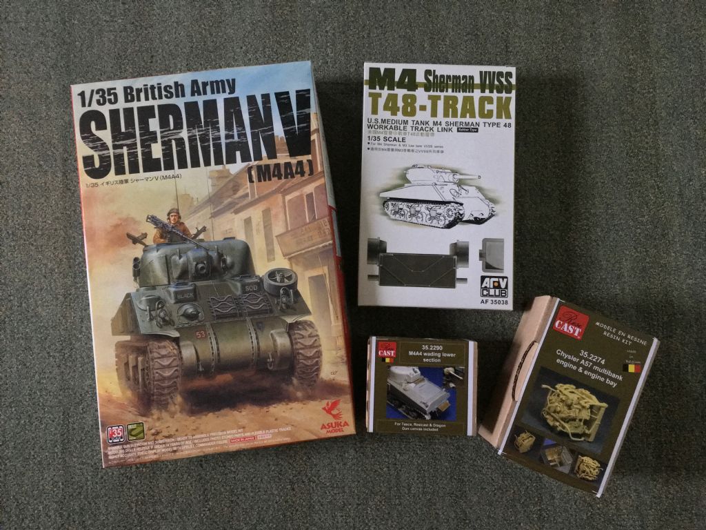
    Now that my Churchill AVRE is ready for painting, I figure I can start on the next model without too much risk of never finishing the previous one. Let me begin by placing this one in a historical context too …

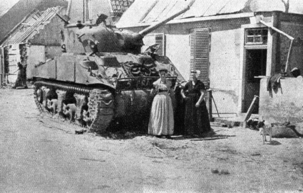
    Here is a photo of two tanks in the village of Westkapelle, the Netherlands, taken circa 1946:


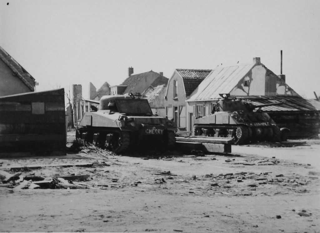
    (photo by Neeltje Flipse-Roelse, via Beeldbank Zeeland)

    Those who’ve read my posts on the AVRE model may recognise the location by the house in the middle of the picture. Yes, this is just a short distance away from where the AVRE stood — it’s entirely hidden by the Sherman on the left in this photo. At present, this same site looks like this:


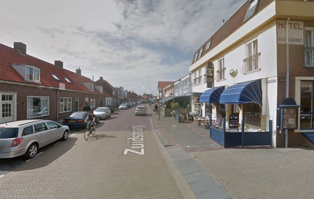
    (source: Google Maps)

    Note the angle is different because Google Maps won’t let you see the street from the pavement for some odd reason … The tank on the right was located approximately where the covered outdoor seating area, in the middle of the photo, is now; the cyclist would be more or less passing the tank on the left in the 1940s photo.

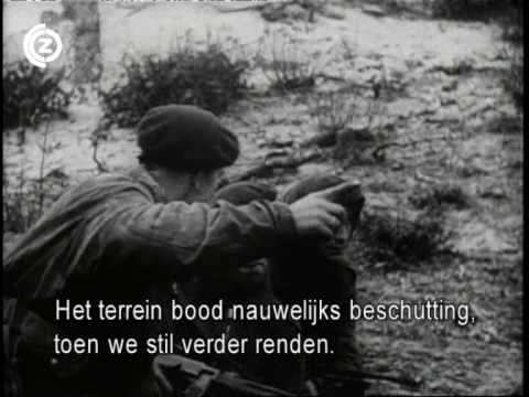
    How did those tanks end up there? Good question … On the morning of 1 November 1944, this happened on the beach a few hundred meters from where these photos were taken:
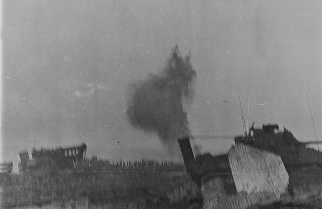

    (source: unknown)

    The tank on the right is the one on the left in the post-war photograph. (How can I tell this from a blurry picture? Too much staring at too many photos like these in recent weeks and thinking about what’s actually in them )

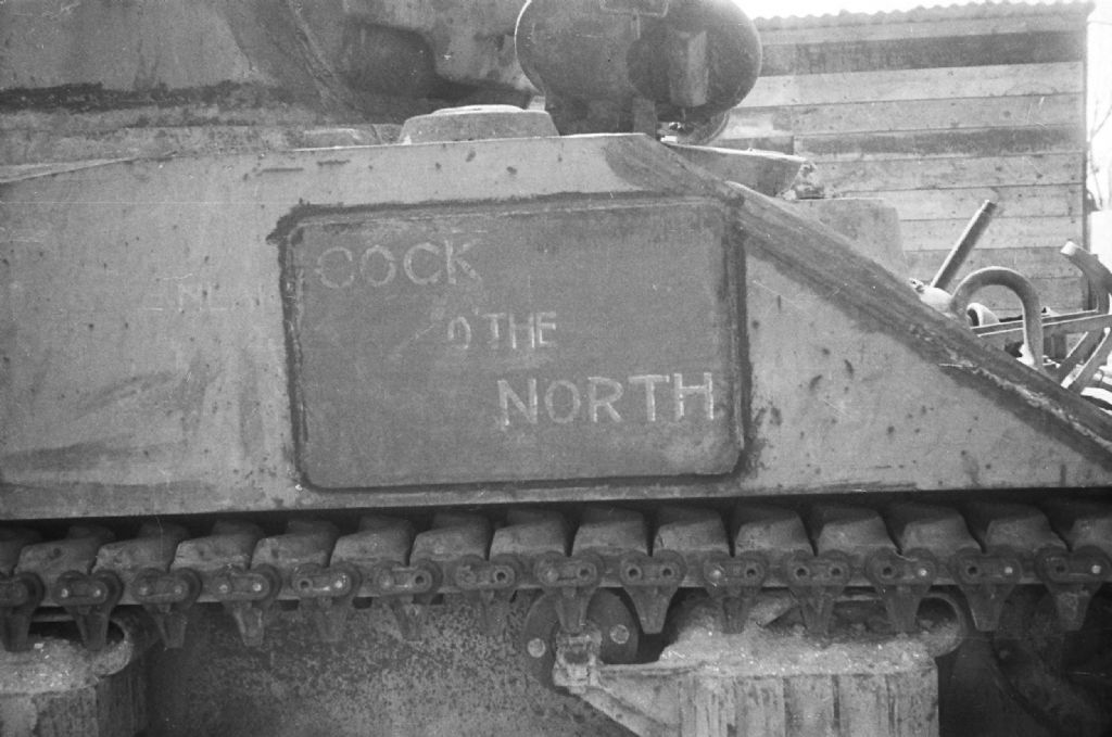
    In all, two Sherman Mk. Vs, at least six Sherman Crab Mk. Is, and at least five Churchill Mk. IV AVREs were landed on the beach at Westkapelle, plus a multitude of Buffalo and Weasel amphibious vehicles, as well as more than two full Commandos — that’s not two guys, but two battalion-size units. Much of the armour bogged down on the beach, so that by the next day, three AVREs and two Shermans (both the non-Crabs) were all that was left operational. These were sent northeast, to the village of Domburg where German resistance was holding up the Commandos’ advance. Here is the tank that’s on the right in the first photo, likely in Domburg:
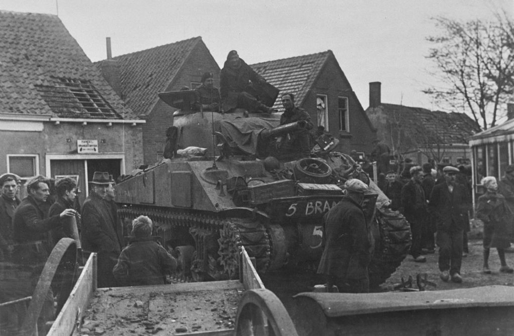

    (source: unknown)

    Other photos show that the other tank was a bit behind it, in front of the house with the two upper-floor windows, around the time this picture was taken.

    And this is both of the Shermans in action, probably east of Domburg:
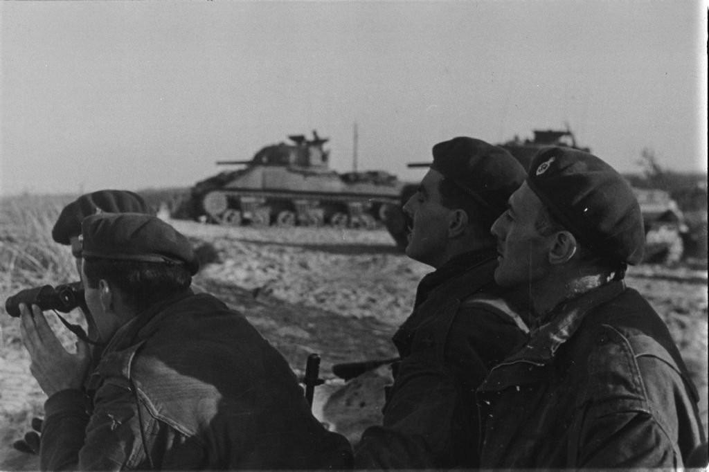

    (source: unknown)

    The tank in the middle is the one on the right of the first photo I posted, the tank on the right is, well, the other one, given that there were only two Sherman Vs. The men in the foreground are probably Belgians from No. 4 Troop, No. 10 (Inter-Allied) Commando.

    According to Nigel Duncan in 79th Armoured Division: Hobo’s Funnies (Windsor: Profile Publications, 1972), just these two tanks fired about 1,400 rounds of HE and “a large amount of AP shot” in the course of a week’s worth of fighting …
  • Guest

    #2
    (Originally posted by me on the Military Modelling forums on 31/03/2018 19:41:23)

    After the fighting, the tanks seem to have been driven back to Westkapelle, where they were parked along the side of the Zuidstraat (that translates as “South Street” in English), the main street through the village, then as now. They were photographed multiple times before eventually being removed, probably around 1948. For example, here are two local women (in traditional dress) posing in front of one of them:


    In 1947, the Royal Netherlands Army also sent photographers to record the tanks left in the village:


    (source: NIMH)

    This is apparently one Sgt. Bierhuis, Army photographer, posing by the other tank than the one in the previous photo. The NIMH’s caption wrongly states the tank as having belonged to the 52nd (Lowland) Division, probably because of the “52” arm of service marking it carried. In fact, all the Shermans in Westkapelle were from A Squadron, 1st Lothians and Border Horse, 79th Armoured Division.

    Most people seeing photos like these assume that “Bramble” and “Cherry” are the tanks’ names, given how prominently those words are painted onto them. However, those are actually the codenames of the landing craft they were carried in, and the numbers refer to the same craft: LCT 650 was 6 “Cherry” and LCT 737 was 5 “Bramble”, and all of the Shermans carried in the craft had the same name and number painted on. The tank marked “6 Cherry” was actually named:—


    (source: NIMH)

    And that’s the one I intend to build, in the state it’s in in these photos.

    Comment

    • Guest

      #3
      (Originally posted by me on the Military Modelling forums on 31/03/2018 19:49:09)

      Model photos will have to wait until I’ve gotten round to actually starting building, but I can share a picture already of what I’ve gathered to build this tank:


      An Asuka Sherman V, AFV Club T48 tracks, Resicast deep-wading trunk (lower section only) and a Resicast engine. The plan is to build the kit with the engine deck open, since several photos of the tanks show them like that — like, for instance, the first one in the opening post of this thread — and to add rudimentary internals for the driver’s compartment, as the hatches to that will be left open as well.

      Comment

      • Guest

        #4
        (Originally posted by me on the Military Modelling forums on 02/04/2018 18:15:06)

        Started on the model, with the hull because the engine has to go in it. The Asuka kit has a lower hull that assembles from separate panels, and since Resicast provides a replacement firewall and hull rear, I couldn’t add those for rigidity. Instead, I built the basic transmission housing and glued that to the hull to keep things square, and added the Asuka firewall without glue:


        Once that had dried I could add the Resicast photo-etched floor and hull side detail panels. Unfortunately the side panels were warped, probably because half their thickness has been etched away over most of the surface area, to create raised detail. After carefully bending them as flat as I could get them, I still had to clamp them to the model, with a ruler between the clamps and the etched part to apply pressure over the whole panel:


        With that done, the panel aligns well enough with the plastic hull side:

        Comment

        • Guest

          #5
          (Originally posted by me on the Military Modelling forums on 09/04/2018 19:55:32)

          Progress is a little slow, but I’ve been working on the engine bay some more. The first thing I noticed is that the Resicast replacement rear plate is too narrow:


          I’m guessing the master was made from an Asuka plastic part, and it’s shrunk as part of the resin casting process. The difference between the two is too noticeable on the model to be able to use the Resicast part, if you ask me:


          That meant building the internal details on the rear plate myself, mainly using brass rod, copper wire, and some bits of plastic card and rod, plus the Resicast fire extinguisher nozzles of course:


          I had already noticed in the photos of the real tank and the Tech Manual illustrations included in Resicast’s instruction sheet, that there seems to be more plumbing in the engine compartment than the engine set provides, and some of it runs in different directions than Resicast would have you put it. A little searching turned up a very good quality scan of US Army TM9-754: Medium Tank M4A4, courtesy of Google, which includes a better (larger) version of an illustration Resicast also provides:—


          In addition, I’m not convinced that resin is the ideal medium to provide this pipework in, given that the parts are about half a millimetre thick. Copper wire to the rescue!


          All the grey bits are of course Resicast parts, but the brown and red wires are different thicknesses of copper wire, which I salvaged from various electronics devices (hence the coloured varnish).

          You may notice that I’ve put the plastic firewall in anyway, and the pipework I added ends before it gets there. This is because I realised that the radiator is so big that it blocks all view of the firewall when the forward part of the engine deck is in place. The fuel tanks visible in the photos above will also end up being invisible when the model is finished, but I had already glued them in place and they’re stuck too fast to remove without probably damaging the plastic sponson undersides they’re glued to

          Comment

          • Guest

            #6
            (Originally posted by me on the Military Modelling forums on 10/04/2018 18:49:13; this was originally a reply to a question by someone else, so it may come across as a little out of sequence with the previous)

            There’s another photo of [one of these tanks] taken at probably the same time [as one shown earlier] being resupplied with 75-mm ammunition from an LVT (2), printed in 79th Armoured Division: Hobo’s Funnies that I mentioned earlier. A-ha, here it is:


            (source: oorlogzeeland.nl)

            There are also more photos of the tanks with the Commandos, but the one that seems to usually get printed only shows “5 Bramble” in the background. Unfortunately I can’t seem to find any photos from that series online just now, but while looking for them, I did come across a scan of this photo that seems relevant to share here:


            (source: Strijdbewijs.nl)

            That’s the same tank again, firing on German positions in Domburg.

            Comment

            • Guest

              #7
              (Originally posted by me on the Military Modelling forums on 10/04/2018 19:34:21)

              Some more digging turned up the source of the pictures: the film taken by Norwegian Commando P.G. Jonson. It’s on YouTube:


              Shermans to be seen at 2:32, 4:07, 4:23, 4:45 and 6:37. Other vehicles in the film are LVTs, M29C Weasels, and Churchill AVREs, as well as footage of Hawker Typhoons attacking German positions toward the end.

              Comment

              • Guest

                #8
                (Originally posted by me on the Military Modelling forums on 11/04/2018 09:45:25)

                Originally posted by Hooch on 11/04/2018 08:08:01
                Interesting that they were "named"/designated by their LVT.

                So after they had completed their engineering work, they just left them for 3 or so years at a town after the war?
                LCT, not LVT — it’s a difference of about 200 tonnes and a pair of tracks I also didn’t know this for a long time, but yes, for some reason the Shermans (including the Crabs) had the landing craft name and number, but the Churchill AVREs and armoured D7 bulldozers don’t seem to have, even though they were carried in the same four LCTs as the Shermans.

                As for the tanks simply being abandoned: yes, that’s the impression I get from studying photographs. I know of one photo of a Crab in Westkapelle with what appear to be two of its crewmen sitting on the front, so taken during or just after the fighting, but this same Crab was left elsewhere in the village; the two Sherman Vs fought at Domburg, yet both ended up in Westkapelle again. My theory is that after the last Germans on Walcheren surrendered on 8 November 1944, the crews were ordered back to Westkapelle to ship out, but for some reason were told to leave their vehicles behind. This mainly because they were parked close together and fairly neatly by the sides of the street.

                Unfortunately it would be hard to find eye witnesses (or statements) to support this idea, given that the village was pretty much entirely deserted after the British bombings of early and mid October. There were six or seven people in Westkapelle when the landings happened on 1 November (one of them a great-grandfather of mine), and I doubt there would have been many more a week later.

                Comment

                • Guest

                  #9
                  (Originally posted by me on the Military Modelling forums on 14/04/2018 18:22:17)

                  I’ve now started building the engine and suspension. Here’s the basic engine from the front:


                  And from the rear:


                  Unfortunately, this is the easy bit A central piece, five engine blocks and front and rear panels. Now all I need to add is the radiator plus all the parts for the pipework, plumbing, carburettors, and what have you that goes around the outside of this basic engine assembly. Oh, and figure out what I can add before painting, and what I’d best leave off until after.

                  As for the suspension, there’s not really all that much to do:


                  The bogies are fully articulated, and Asuka would have you cut little rectangles of a rubber sheet (provided in the kit) to go inside the bogie body (or “bracket” as the Sherman’s TM calls it) so that the whole thing actually springs. I don’t want that, but unfortunately the kit’s instructions don’t provide any alternatives. However, the box does include two of these sprues:


                  … without mentioning what they’re for at all. As the plates fit nicely into the space for the rubber sheet inside the bogie body, I concluded that that’s what they’re intended for. The difference between A, B, and C is the thickness: C is just a plate, B is the same plate with two 0.5 mm nodules on it, while on A the nodules are 1 mm thick. Strangely there are four As and four Bs on each sprue but only two Cs, and I felt that using only A or B+C was too low, while A+B didn’t fit. That left me with A+C, which just fit inside the bogie but required a clamp to keep the bogie together while the glue set. (As I only had four Cs for six bogies, I just shaved the nodules off two Bs for the remainder.)

                  Other than that, all I did was drill four holes on the front face of each bogie:


                  These represent the bolt holes for the return roller, since the bracket of that could go on either side — the bogie bodies were the exact same on the left and right sides of the real tank, just the direction of the skid on top and the side that the return roller was bolted onto differed. I drilled them by eye, but maybe I should make a template of some kind for future Shermans to make sure they’re all the same, as these six obviously aren’t if you look (too) closely.

                  The road wheels, incidentally, had a very awkward moulding seam running down the middle. I first tried scraping it off with a knife, but found that slight shrinkage of the wheel meant that I was scraping the edges down but not the seam. I therefore took the wheels to my father’s lathe and turned them down just enough to get rid of the seam.

                  I had to do the idler wheels by hand, as the solid ones don’t have a hole in them that I could put a bolt through to hold the wheel in the lathe. By the time I’d finished those my thumbs hurt enough from holding the wheels that I was glad I didn’t have to do the same with twelve roadwheels as well.

                  Comment

                  • Guest

                    #10
                    (Originally posted by me on the Military Modelling forums on 18/04/2018 18:15:13)

                    I figured it’d be best to paint the engine before adding most of the tubes (air intakes, exhausts, etc.) to it, and while the radiator is still separate. The question is: what colours would those be? This site has good photos of a restored engine, which is painted a kind of olive green/drab, with all the coolant and fuel pipes black and the exhaust pipes silver-grey. Lacking any better information, other than that the engine seems fairly dark in black and white photos, I decided to use the same scheme.


                    This is the engine painted Tamiya XF-62 olive drab, but I think it’s too dark. The light bits are parts I added after painting the basic engine block, most of which need to be the same colour as the rest of the engine. The radiator is simply matt black overall right now, but it needs some highlighting so the detail will hopefully be visible a little when it’s inside the tank. Much the same goes for the engine.

                    All the other plumbing that goes around it, I’ll add once the main body of the engine has the right colours and the radiator is glued to it, as I doubt it’ll be possible to get a brush in there when everything is in place.

                    Comment

                    • Steve Jones
                      • Apr 2018
                      • 6615

                      #11
                      Jakko
                      I am glad you managed to bring this one over from MM. Looking forward to seeing this one to the end. Good luck
                      Steve

                      Comment

                      • Guest

                        #12
                        (Originally posted by me on the Military Modelling forums on 18/04/2018 19:54:16)

                        Because the engine is taking so long, I’ve built the turret in the mean time.


                        It’s mostly straight from the box, with added tie-downs to the front sides from 0.5 mm plastic rod and the brackets for the rear stowage box from some plastic strip, as well as an extra antenna mount on the right rear that I made from a piece of photoetched fret. (I must add that I can’t be 100% sure the antenna base should be there because I don’t have any photos that show the right rear of the turret, but the other Sherman V in Westkapelle had it, and the two seem to be almost identical in their details, so I added it to the model.)

                        I looked through my pile of empty, or nearly so, frets for a section that was wide enough for the antenna base (left over from my Churchill AVRE), with a narrow bit coming off it. I cut a bit off, wider than the base, and then squared it up by making a shallow cut into it with a hobby knife along a steel ruler, then gripping the piece in flat-nosed pliers so that the cut I made was along the edge of the pliers, then using tweezers to wobble the free end up and down until metal fatigue snapped it off.

                        The bracket on the right side, for the smoke grenade launchers, is tricky to align because Asuka doesn’t give any moulded location holes or anything. The instructions include a good drawing of where it should go, but they leave it up to you to work out how to transfer that information to the model. I did it by putting the gun horizontal and drawing a pencil line on the turret side at the level of the middle of the barrel, which positions the bottom end of the bracket. I then added a vertical line just to the rear of the front of the commander’s hatch to locate the fore-and-aft position. That left the 30° angle the bracket should be fixed at. Luckily, this is easy with a ruler: I measured 10 mm up on the vertical line from the bottom of the bracket, then 5 mm to the rear, and marked that spot. A diagonal line through that point and the intersection of the vertical and horizontal lined then nicely gives the correct angle — or at least, correct enough for my standards (This is because a right-angled triangle in which one of the right-angled sides is twice as long as the other, has a 30° angle between the long and the diagonal sides.)

                        The hole in the commander’s hatch is because on the real tank, the periscope and its entire mounting appears to have been taken by (probably British) soldiers on a salvage mission — all the Shermans in Westkapelle are missing all their periscopes in most post-war photos, and have a big hole in the commander’s hatch like on the model.


                        This turned out to be easier to do than I had anticipated. I used a fine fret saw to cut inside the outer line of the periscope, then used a half-round file to remove the rest of the material to the line moulded into the hatch. It didn’t come out perfectly round, but you only see that if you’re looking very closely.

                        Comment

                        • Guest

                          #13
                          By now the interior is largely, but not quite, finished:


                          I made two principal mistakes here. The first is that I had expected to just stick in a transmission, some seats, driver’s handles, and be done. It turns out you can see an awful lot of the interior through those small hatches in the front roof, hence all the extra stuff — and there’s more to add, like the ammo bin behind the assistant driver’s seat, an ammo rack to the left of the driver, the shelf over the transmission, the ammo rack holder for the bow machine gun, the underside of the turret basket, and some more bits and pieces. The seats are built, but not attached because I don’t want them to get in the way for building and painting.

                          The second mistake was using an AFV Club M10 3-inch GMC for the interior parts, when that includes no more than the transmission and seats; apparently the Academy M10 has a much more complete interior, which would probably have saved me a fair amount of work on building the driver’s controls. (As I had to buy an M10 kit for these parts, I picked the wrong one to order.)

                          My advice: buy a resin interior set, like the one from Resicast or whatever other brands offer them, if you want to have a Sherman with the drivers’ hatches open.

                          Comment

                          • Guest

                            #14

                            Comment

                            • Tim Marlow
                              SMF Supporters
                              • Apr 2018
                              • 18907
                              • Tim
                              • Somerset UK

                              #15
                              Cool, I’ll get to see this one finish as well

                              Comment

                              Working...