Scale Model Shop

Collapse

Churchill SBG Bridgelayer

Collapse
This topic is closed.
X
X
 
  • Time
  • Show
Clear All
new posts
  • Guest

    #1

    Churchill SBG Bridgelayer

    Bit of nostalgia modelling, I first built the bridgelayer back in 1980, when the Tamiya Churchill was just a baby, so armed with one kit, loads of 1/16th thick black plasticard (you took what you could get back then) and plans for a 1/76 scale AVRE I set about the build. Rebuilt the turret, scratch built the rest except for the hull and running gear.
    Fast forward to today.
    I started this build some time ago but using the AFV Club AVRE Mk.IV version, and as with a lot of our models along came something new, I had already done the girl and 'boy' racer stuff so it had to be another model and/or work that sidelined the build.
    So it has now resurfaced and is in build mode, with today work starting on the bridge itself, and as you can see from the last photo it is going to take a couple of days just to get the angle strips in place.
    Cheers,
    MikeC.
    [ATTACH]306031[/ATTACH]

    [ATTACH]306033[/ATTACH]

    [ATTACH]306034[/ATTACH]

    [ATTACH]306035[/ATTACH]

    [ATTACH]306036[/ATTACH]
  • grumpa
    • Jan 2015
    • 6142

    #2
    Great subject, and dedication to scratch building!
    Am gonna watch this one :thumb2:

    Jim

    Comment

    • Jim R
      SMF Supporters
      • Apr 2018
      • 15679
      • Jim
      • Shropshire

      #3
      Hi Mike
      That looks just so neat and sorted. great stuff.
      Jim

      Comment

      • Guest

        #4
        Hi Mike is this the bridge you are building if it is this might help if not sorry.

        Tank Bridge, Small Box Girder

        Tank Bridge Small Box Girder or SBG Assault Bridge. Introduced specifically for D Day and the 79th Armoured Division it was designed to support a Class 40 load over a 30 foot span, or more specifically a 12 foot high sea wall.

        The bridge itself consisted of 4 Small Box Girder hornbeam sections connected together to form a twin trackway bridge, connected with crossbeams.
        Churchill AVRE with Small Box Girder Bridge

        Churchill AVRE with Small Box Girder Bridge
        Unlike the Number 1 and Number 2, it was carried by a standard Armoured Vehicle Royal Engineers (AVRE), not a specialised bridgelayer and thus the carrying vehicle was able to be used in other engineering roles once the bridge had been detached.

        The sequence of operation on a sea wall is shown below, including using a fascine to cushion the fall!

        Churchill Assault Vehicle Royal Engineers (AVRE) SBG Bridge


        A Mark II variant introduced a more sophisticated launching mechanism that provided for a more controlled release.

        The bridges were carried on a small bogey trailer towed behind the tank and attached to the front prior to use.
        Armoured Ramp Carrier (ARK)
        The Armoured Ramp Carrier or ARK was used for crossing small gaps and used in a number of variants. At its simplest, an ARK was a tank with its turret removed and ramps fitted to the top of the superstructure and at either end of the hull.
        The vehicle would be driven into the gap, deploy its ramps and other vehicles simply driven over the top of it. The original ARK’s were designed to enable other tanks to climb sea walls on the beach defences on D Day although it is not certain if any were actually used.
        ARK Mark I, used in the D Day landings primarily for traversing the sea walls and defences it had a 2 foot wide wooden trackway with short ramps and about 50 were manufactured.

        Pete.

        Comment

        • Guest

          #5
          Here’s one that’s not gone quite right:

          [ATTACH]306160[/ATTACH]

          And what one looks like if you leave it out under those conditions for a year or so:

          [ATTACH]306161[/ATTACH]

          (Different tank, but only at most a few dozen meters away from the other one.)

          Comment

          • Steve Jones
            • Apr 2018
            • 6615

            #6
            Mike

            This should be fun! Rather you than me. I wish you all the best and will follow on avidly taking notes

            Steve

            Comment

            • Guest

              #7
              Pete,
              Many thanks for the photo's and information. That is the bridge that will be built. It is basically a re-incarnation of my first model which vanished some time ago and so I thought it time to get building a new(er) model.
              Jakko,
              Again thanks for the photo's. I think the top one was taken on the morning following the storm that hit the beaches.
              Steve,
              It is not as bad as it looks, it is just the repetition that gets you, but thankfully I am almost over that stage.:flushed:.
              Cheers,
              Mike.

              Comment

              • Guest

                #8
                Originally posted by MikeC
                Jakko,
                Again thanks for the photo's. I think the top one was taken on the morning following the storm that hit the beaches.
                Um, no?

                [ATTACH]306204[/ATTACH]

                The one on its side is the same tank, after being battered by the sea for longer. The location is:

                [ATTACH]306205[/ATTACH]

                That photo was taken from the top of one of the caissons. The rolled-over AVRE is just out of shot to the right but the SBG bridge can be seen at the edge of the photo.

                Comment

                • Guest

                  #9
                  Jakko,
                  Many thanks for the photos and explanations of the locations.
                  Cheers, Mike.

                  Comment

                  • Guest

                    #10
                    Update....
                    Series of photos showing the main construction of the bridge sections all that is to be added are the smaller details and the inner cross plates as the one at the front.
                    Cheers, Mike.
                    [ATTACH]307158[/ATTACH]
                    [ATTACH]307159[/ATTACH]
                    [ATTACH]307160[/ATTACH]
                    [ATTACH]307161[/ATTACH]
                    [ATTACH]307162[/ATTACH]
                    [ATTACH]307163[/ATTACH]

                    Comment

                    • Mickc1440
                      SMF Supporters
                      • Apr 2018
                      • 4775

                      #11
                      That's some very nice scratchery Mike.

                      Comment

                      • Guest

                        #12
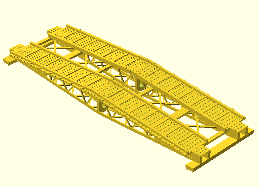
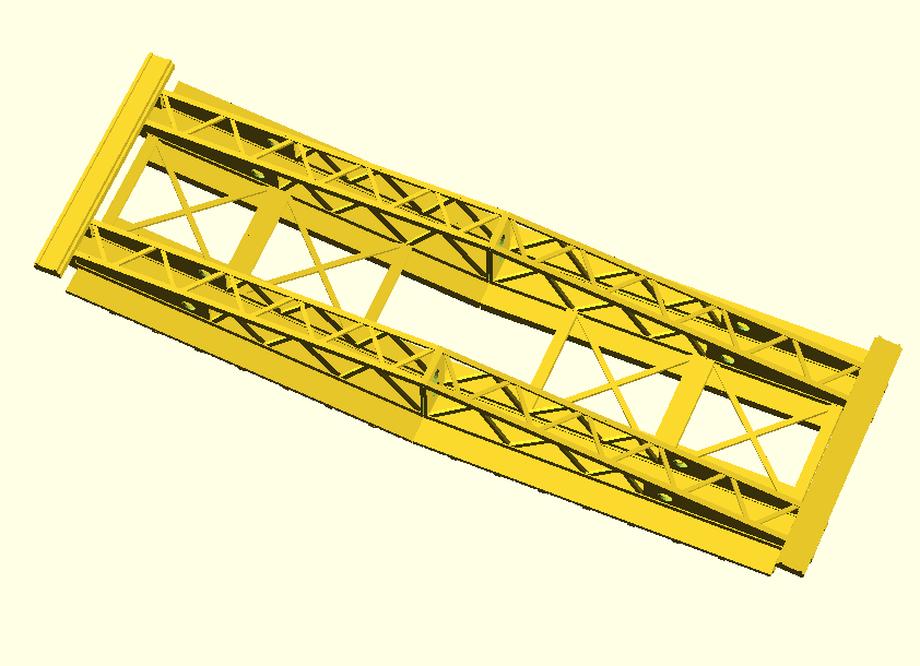
                        That’s looking pretty impressive. Mind if I ask what you’re using as references? Some years ago I built most of a 3D model of an SBG to have it 3D-printed in 1/72 scale, but couldn’t really find sufficient details on the ends of the bridge, so never finished it.


                        Comment

                        • Guest

                          #13
                          Jakko,
                          Those are nice renderings. I will sort out the end dimensions and sketches. I know for a fact that in 1/35 scale from the end of the treadway it is 11mm to the end of the narrow end section (if that makes sense) which is the part that the end beams are sitting on and the width if the lattice work frame. The drawings i have worked from in the past are the G.W. Futter 1/76 scale that appeared in the early editions of Military Modelling magazine and led to a now defunct book called "The Funnies". And that is where most of my original reference came from, since then we have been given the internet and that has helped a lot, but sadly not in the case of the bridges. If you would like copies of the Futter drawings, please pm your email and I will scan and send them to you.
                          Cheers, Mike.

                          Comment

                          • Peter Gillson
                            SMF Supporters
                            • Apr 2018
                            • 2594

                            #14
                            Some excellent scratchbuilding - you are a braver man than I taking on tbis in 1/35. I am enjoying followign and seeing each stage

                            Comment

                            • Guest

                              #15
                              Originally posted by MikeC
                              The drawings i have worked from in the past are the G.W. Futter 1/76 scale that appeared in the early editions of Military Modelling magazine and led to a now defunct book called "The Funnies".
                              I have that book, and unfortunately the bridge in the drawings in it is somewhat inaccurate, especially the width of the girders My 3D model is actually based mostly on the Matchbox 1/76th scale one, which seems to be more accurate than Mr. Futter’s drawings, when I compared it to photos I found online and in the same book.

                              Comment

                              Working...