If this is your first visit, be sure to
check out the FAQ by clicking the
link above. You may have to register
before you can post: click the register link above to proceed. To start viewing messages,
select the forum that you want to visit from the selection below.
Most of it’s straightforward, but the racks with spare sprocket rings on the sides are a little tricky. There are no locating points for the lower bracket, but the upper part goes into two thingies that do have them, so it’s simpler to fit the upper one first. Then put in the sprocket(s) with three teeth up and the two teeth that point down just above the strip that’s glued to the lower hull edge. That done, you can fit the lower bracket against the sprockets, so that the pins on it fit in the hollows between the sprocket teeth. There’s still some fiddly work to get it all lined up that could have been avoided if Tasca had moulded some notches in the side, though …
On the back you can see I replaced some of the spare track links by a different type from my spares box, for variety.
In the Bold Division T1E1 mine roller conversion set, the hubs aren’t correct. What you get is seven hubs per set of six discs: one for each disc, plus one to go on the outside. On the real thing, though, there are two hubs per disc, one on each side. This is clearly visible because the hub consists of spokes against the disc and a ring on the outside of the spokes — but with the Bold Division parts, you will only get spokes on one side of each disc, except the one at the end that will have spokes on both sides.
I first looked at modifying the resin parts, but that’s a no-go for several reasons. One is that it would be very hard to thin down the hub parts to make room for spokes on the other side. The second is that the hole in the centre is too small, so they would also need to be drilled out. Last, the shapes and dimensions of the spokes are off a little. I know all this because over on Missing-Lynx, someone gave me this scan from the technical manual for the T1E1 mine roller:
[ATTACH]457736[/ATTACH]
Since the diameter of the disc is known (122 cm), I could work out the dimensions of the rest easily enough by doing some measuring in Photoshop. I first intended to scratchbuild the hubs, but couldn’t find a way to make the rings except by laboriously cutting them from plastic card with compass cutters — no, thanks, for 36 rings = 72 circular cuts … I can’t even make one that isn’t a spiral, never mind that many. At least. So, I turned to computer-aided design:
[ATTACH]457737[/ATTACH]
After a request on another forum, someone kindly printed up this for me from that drawing:
I need 36 hubs, so he printed 45 of them (minus one that didn’t come out right) in case I break some Here is a comparison between the Bold Division hub on the left and the one I designed on the right:
[ATTACH]457739[/ATTACH]
That just left one more problem to solve: the hole in the centre of the disc is 5 mm on the kit parts, but needs to be 9 mm to match the real thing. The reason for that is because the real vehicle had an oversize hole for the axle — as you can see in the TM illustration above. Once you know that, on level ground, the axle lies at the bottom of the hole though the discs, you spot it immediately, asi n this photo I posted earlier:
If you look closely at the roller on the left of the vehicle, you can see the axle hub is clearly below the centre of the rollers. Even more tellingly, one of the outer discs of the front roller is further forward than the other five, which can only happen if the hole through it is bigger than the axle (and the crane is actually lifting the arm up a little).
All this, by the way, is so that the discs would conform to uneven ground and not hover over mines laid in hollows in the ground.
Enlarging the holes proved easy enough using the table drill in my father’s shed:
[ATTACH]457740[/ATTACH]
The stepped drill is 4 mm, 6 mm and then 9 mm (plus bigger above that) so it had the size I needed, but centering it proved slightly tricky because the hole in the plastic discs was 5 mm, so I had to centre it by eye and press the disc firmly down onto the wood with my index and middle fingers while trying not to hit them with the bigger parts of the drill
But look at the improvement you get for that work:
[ATTACH]457738[/ATTACH]
Another small thing wrong with the conversion kit is that the big bar that goes across the front of the tank, was bent:
[ATTACH]457741[/ATTACH]
This, I solved by heating it with a hair dryer, rotating it a few millimetres in front of it so it would heat up on all sides, and doing that long enough so the insides would get hot as well. Once I thought I had achieved that, I pressed it down flat onto a stone kitchen countertop and held it there until it cooled. That seems to have worked well enough
Hi Jakko
Excellent research. Really admire your ability to interpret these reference photos. Clear when you point it out but I'd not see it for myself.
Those printed hubs really look the part. Scratching 36 would have been a nightmare.
Glad the bent bar straightened ok.
Jim
I hadn’t spotted that the hole is notably larger than the axle until that TM picture, and then wondered if it was right or if I was missing something. Only when someone posted some frames of a film of a T1E1 driving over rough terrain, to show that yes, the hole is bigger than the axle, did all the pieces fall together for me At that point I looked back at other photos and noticed the low axle hub there as well, bit I hadn’t spotted it before. Like I said, obvious once you know it, but before then …
That's coming on nicely. Those 3D rollers do look very good indeed.
I do have one very daft question though.....
This is very not obviously a 'gun' tank in the same way other Sherman conversions/adaptions were, for example the crab/flail but could the turret still rotate? Not sure why it would need to for its intended use but just wondered.
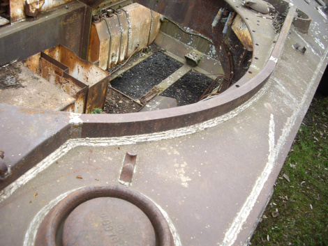
The turret was bolted down, it couldn’t rotate at all. The Sherman turret ring had a row of holes around it anyway, to which the turret race (the track with ball bearings) was bolted on gun tanks. They’re visible on this M4A2 hull:
What I find kind of odd is that the US Army called the M32’s turret, well, “turret” despite the fact that it couldn’t rotate. On a tank-like vehicle, “turret” conjures up a picture of a rotating one, but I guess it’s a throwback to the original meaning of the word here
Looking for something I could use to line up the hubs and the discs, I eventually found this:
[ATTACH]458374[/ATTACH]
The black end of this draughting pen fits well in the hole in the hub:
[ATTACH]458375[/ATTACH]
… allowing me to glue the disc to it neatly as well:
[ATTACH]458376[/ATTACH]
Do that eighteen times, leave to dry and do the other side (lining up the spokes by eye) and you have:
[ATTACH]458377[/ATTACH]
Another task tackled. Until you dry-fit things and find that:
[ATTACH]458378[/ATTACH]
… a set of six discs is too wide to fit the Bold Division parts I first thought I might be able to sand down the hubs a little, but the set of six discs is about 4 mm too wide, meaning 1/3 mm has to come off each hub. But the ring on each is only 0.3 mm thick, so that’s a no-go …
I then looked at, and measured in, a drawing in Steve Zaloga’s old Military Modelling article in which he builds this combination in 1:76 scale, and I found that the Bold Division arms are about 2 mm too narrow, altogether. That means that adding another millimetre on each side isn’t that big a deal, so I glued 2 mm plastic card to both sides, after sawing off the square locating pen that was there.
When the glue had dried, I cut them to roughly match the set’s parts:
[ATTACH]458379[/ATTACH]
I still need to file these down to be seamless, but it was getting too hot in my modelling room
Thanks Though one of these days, I would like to build a model that just assembles out of the box without needing any additional work to correct problems …
Comment